DIY Macropad/Streamdeck!
I've been wanting to get into electronics for a long long while, but only recently have I acquired the workbench and tools to actually begin building stuff! I found the .stl files and code for this macropad on thingiverse right here, and I figured it would be a perfect project to help me learn how to solder properly! I didn't have any wire spools, so I just used some of the threaded 22 gauge wire jumpers that came with the Arduino Uno kit I ordered and never opened. It sucked to cut up perfectly good jumpers for a breadboard, but sacrifices HAD to be made!!!
1. First, I had to solder the ground wires for the switches together in a matrix, so I could ground them all with one pin on the Arduino Micro! These were my first soldering attempts ever, and I was pretty skeptical everything was gonna connect, since I've heard how bad cold soldering can be, and I was pretty sure some of my joints were exactly that. However, I verified continuity with my multimeter--everything worked!
2.Then, I soldered every individual pin to pins 2-15 on the micro. Soldering directly to the little microcontroller was an absolute challenge, but I found pre-tinning the wires, and using rosin flux to make it flow easy onto the pins made it SO much easier. less is really more in regards to soldering--I used too much, and had to use a solder sucker to suck up all the excess. The guide lays out exactly which pins go to which switches, but I didn't bother. We'll address this later!
3. After everything looked good, I jammed the front plate into the enclosure and made sure all the wires fit nice and snug! I attatched a usb-C cable to the ardruino, and hot glued it in place to stop the connector from rocking about.
4. It's time to atone for our laziness in step 2, by going back into the .ino file and changing which pins trigger which function key, making it so it lined up neatly from left to right, going from F-13 to F-24! Then, I uploaded the sketch to the arduino, and BOOM! everything wrorked! Now it's time for the finishing touches!
5. I printed out the keycaps with all my different filament spools using concentric infill for the bottom layer, giving it the cool checkered type effect! I plan on making an autohotkey script to really leverage this to it's full potential, but it's already incredibly usedful for all the different shortcuts in programs like blender, sony vegas, and mixxxx, the software I use to broadcast live to KP Radio!
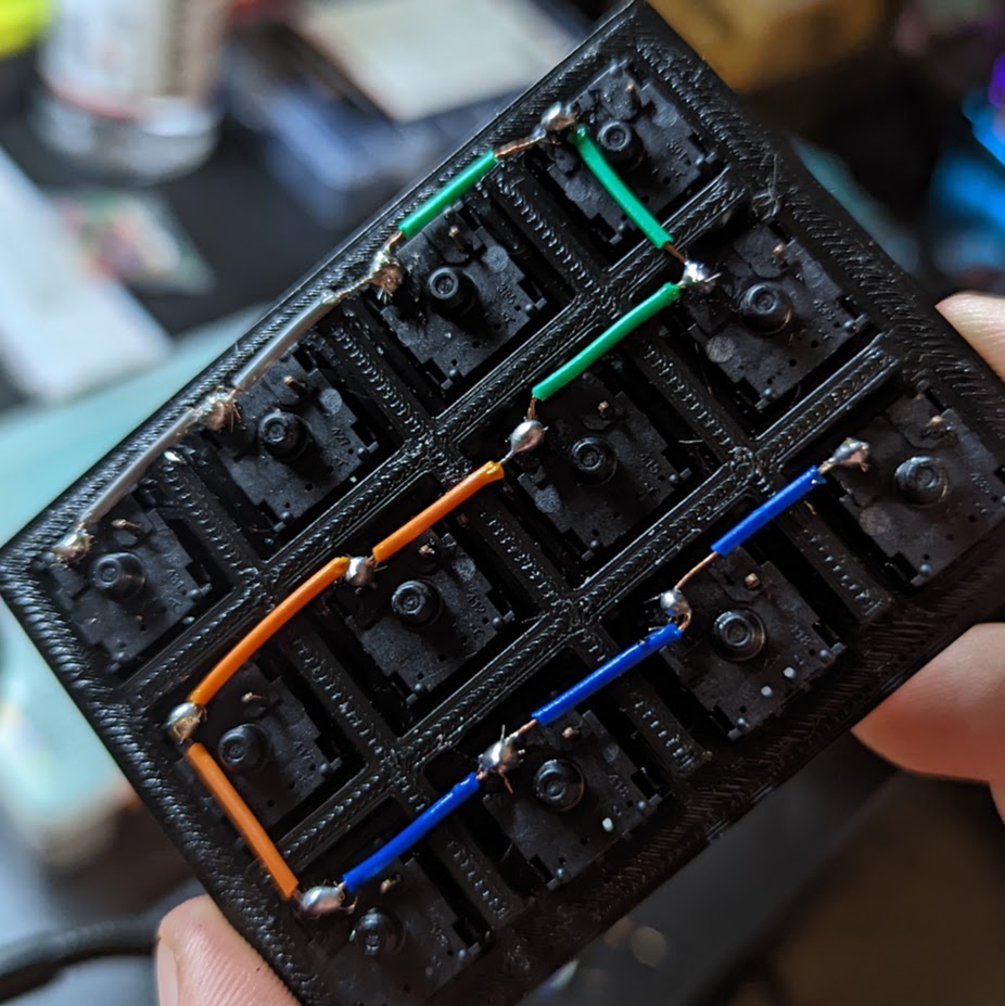
1. Groundwire matrix
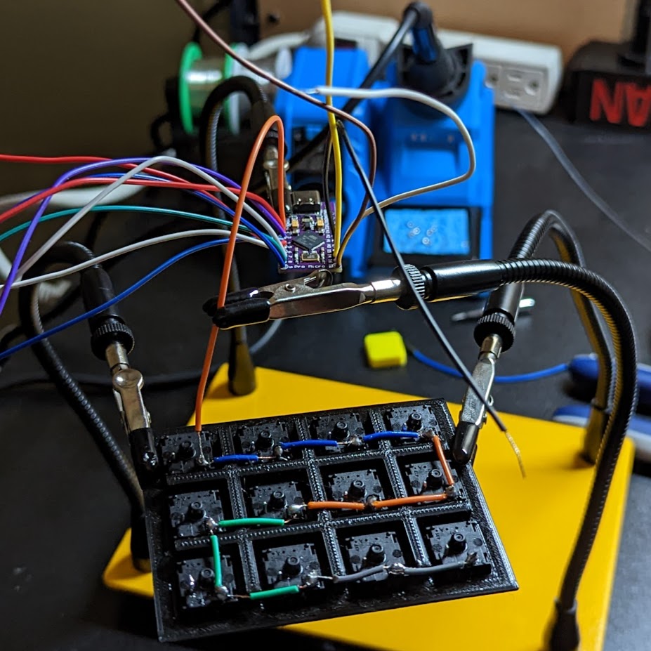
2. Soldering the Micro!
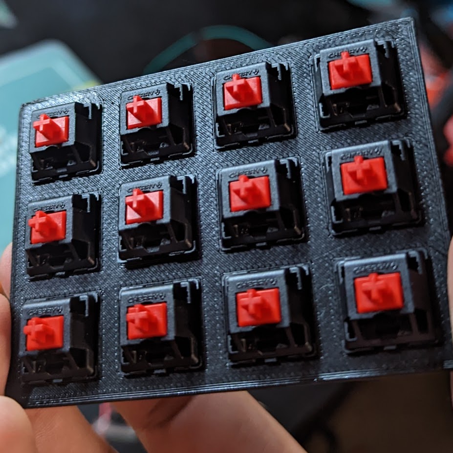
3. Front panel switches
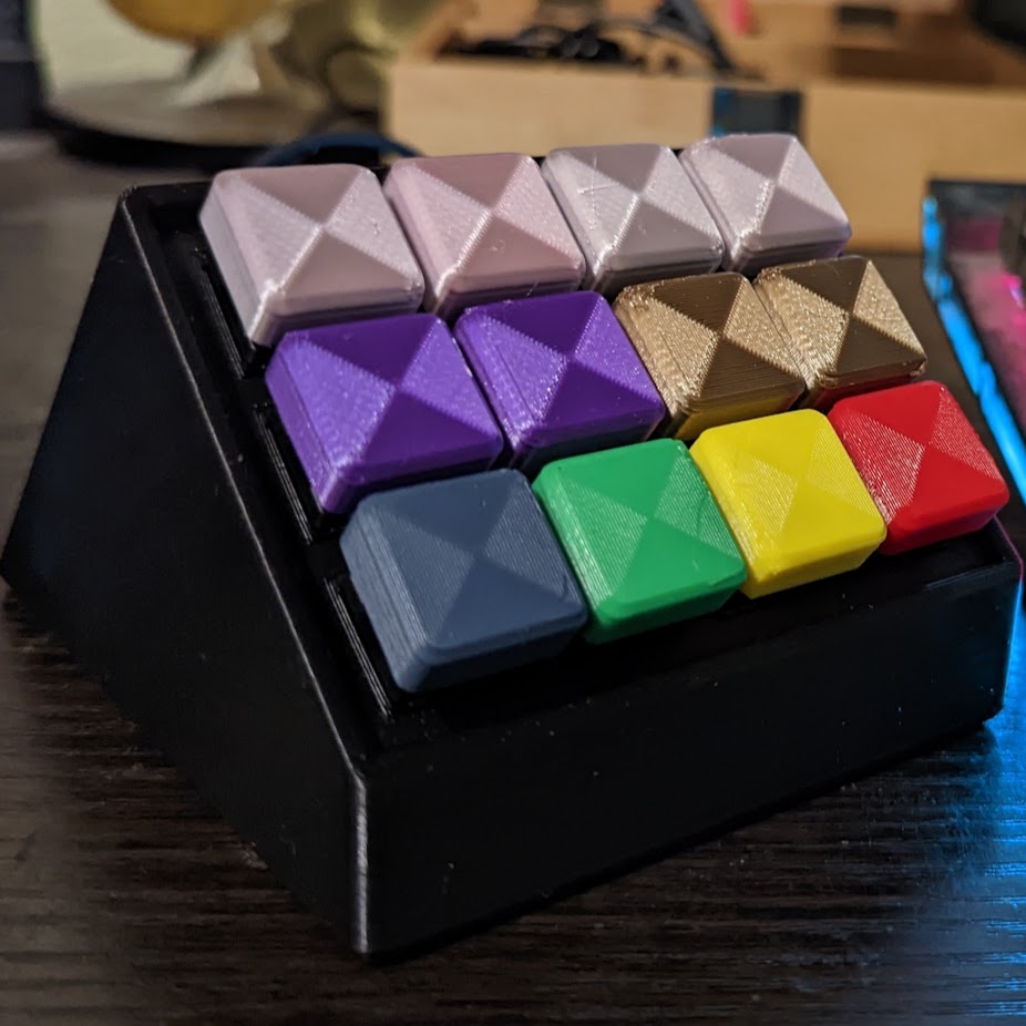
5. Finished product!!!
11/14/2022


